





AirAccess Access Control as a Service Platform with Auto-Cell Networking (ACasS)
Enterprise Hosted Platform - MVPAccess™
New! Napco Access 1 & 2-Door Controllers
Please contact us directly or visit our FAQ page or Video Library.
Toll Free 800-645-9330
Phone 631-842-9400
Fax 631-842-9135
Email: sale@safehomeexpert.com
sale@safehomeexpert.com (Latin America)
Sign up for integrator training seminars. 2 days and 3 day online courses are available from our directory indexed by product.
Learn MoreOffer the one access control solution powerful and flexible enough to protect all of your clients. Continental Access provides state-of-the-art access control software and hardware in an easy-to-implement and easy-to-use access control solution that seamlessly integrate with a wide range of facility management products.
Learn Moresubstation voltage levels can look puzzling when one facility handles several different voltages. A transmission line may enter at hundreds of kilovolts, while nearby distribution equipment supplies homes at much lower levels. The change is visible in the hardware: large transformers, insulated busbars, circuit breakers, and thick conductors connect parts of the grid.
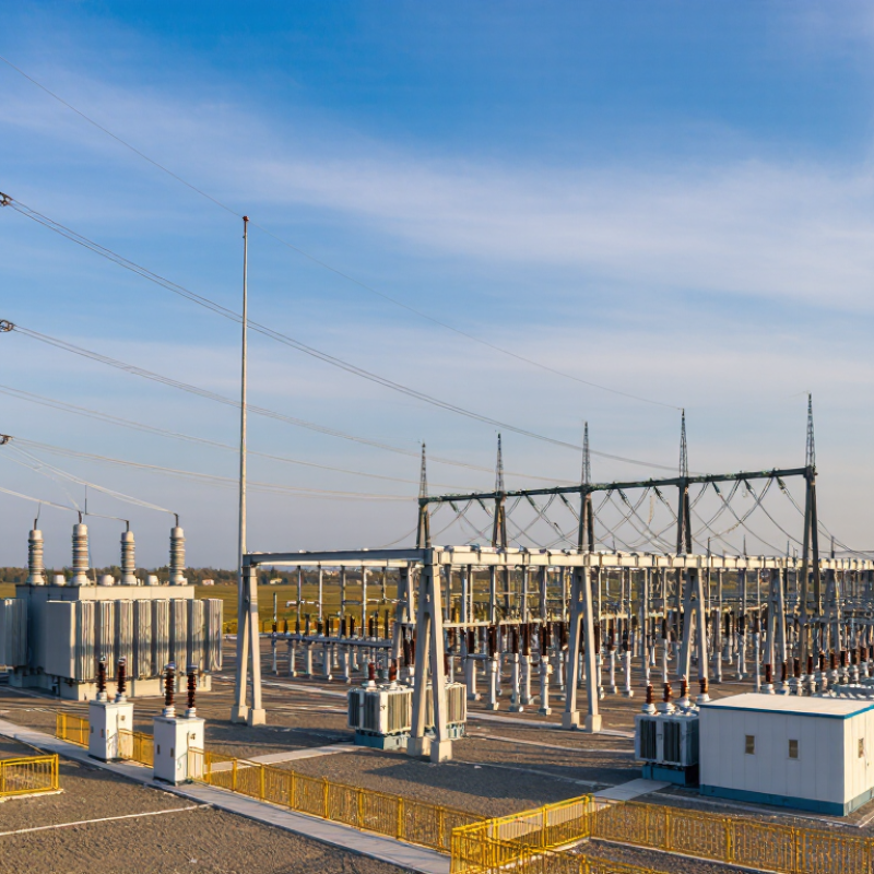
Why are these levels different? Each serves a practical purpose. Higher voltages can move power over long distances with lower current, which helps reduce transmission losses. Substations then use transformers to lower voltage for regional networks and, eventually, local distribution. The precise values depend on the grid, equipment, expected demand, and established utility standards. There is no single voltage plan that fits every place.
Distance matters, but it is not the whole story. A planner must also consider reliability, future load growth, equipment cost, and how a fault could affect neighboring circuits. A transformer’s rating, for example, has to suit both the connected network and the expected flow of power. Safety clearances and insulation requirements change with voltage, too.
It is easy to oversimplify this. Higher voltage is not automatically better; it brings design and maintenance challenges. Local geography and older infrastructure can also shape the levels in service today. Understanding these trade-offs makes substation diagrams easier to read and explains why two nearby facilities may handle power differently.
Electricity moves through a network built for different distances and demands. Near a generating station, a substation uses transformers to raise voltage for long-distance transmission. Higher voltage allows power to travel with less current, reducing energy lost as heat in the lines. At a receiving substation, transformers lower voltage before electricity enters local distribution circuits. The exact levels depend on the regional grid, equipment, and load. There is no single voltage ladder used everywhere.
Substations do more than change voltage. Busbars connect incoming and outgoing circuits, while breakers can isolate a faulted line or equipment. Protection relays detect abnormal conditions and trigger those breakers, helping limit outages. Some substations also switch power between routes or regulate voltage as demand changes. A row of large transformers, humming beside fenced steel structures, makes these functions feel tangible. Small details matter. I find the handoff between transmission and distribution easy to overlook; it is where broad network planning meets the needs of homes, shops, and factories. This explanation is simplified, since substations can serve several roles at once. Their layouts and operating practices vary, so a diagram rarely captures the whole story.
A substation’s voltage level depends mainly on where it sits in the power network. Near a power plant, it may handle high transmission voltages that carry electricity over long distances. Closer to homes or factories, other substations step voltage down for local distribution. The voltage is not chosen in isolation; it must match the lines and equipment connected to the site.
Distance and demand both matter. A long feeder serving a rural area may need a different design from a compact urban network with dense loads. Engineers also consider power losses, expected growth, and the voltage levels used by neighboring substations. Transformer windings, busbars, insulation, and clearances must all be rated for the selected voltage. These details affect cost and the space a station needs. Small choices add up.
There is no single ideal level. A higher voltage can move more power with lower current, but it requires stronger insulation and greater electrical clearances. A lower level may suit shorter routes, yet increase losses when demand is high. Planners compare these trade-offs against reliability needs and existing grid standards. The answer is not always tidy: forecasts can miss how quickly an area changes. That uncertainty is one reason voltage planning must look beyond today’s load.
Voltage levels vary because power systems must balance transmission distance, demand, equipment capability, safety, and compatibility with the surrounding grid. Values below are common examples, not universal standards. AC values are nominal line-to-line RMS voltages.
| Typical Voltage Level | Common Substation Role | Why This Level Is Used | Example of a Voltage Change |
|---|---|---|---|
| 765 kV, 500 kV, or 400 kV | Extra-high-voltage transmission over long distances and between major grid areas. | Higher voltage can carry a given amount of power with lower current, reducing resistive losses and supporting large power transfers. It requires greater insulation clearances and specialized equipment. | 400 kV transmission → 220 kV subtransmission |
| 345 kV, 230 kV, or 220 kV | Bulk transmission, regional grid connections, and delivery to large load centers. | The selected level reflects network capacity, transfer distance, grid planning standards, and the voltage of neighboring transmission circuits. | 230 kV transmission → 115 kV subtransmission |
| 132 kV, 115 kV, or 110 kV | Regional transmission or subtransmission supplying cities, industrial areas, and distribution substations. | This range provides substantial capacity over regional distances while connecting higher-voltage transmission to local distribution networks. | 110 kV subtransmission → 33 kV distribution |
| 66 kV or 33 kV | Subtransmission and primary distribution for towns, industrial customers, and medium-sized load areas. | The choice depends on local demand density, feeder length, required reliability, and the voltage levels already used by the utility. | 33 kV distribution → 11 kV feeders |
| 22 kV, 13.8 kV, or 11 kV | Medium-voltage distribution feeders serving neighborhoods, commercial districts, and smaller industrial loads. | These levels balance feeder capacity and reach with the cost, insulation, protection, and safety requirements of local distribution. | 11 kV feeder → 400/230 V service |
| 400/230 V or 480/277 V | Low-voltage distribution to homes, offices, shops, and many small businesses. | The service voltage follows local electrical standards and the needs of connected equipment. Three-phase and single-phase arrangements differ by region. | 400 V three-phase system → 230 V line-to-neutral supply |
Why Are Substation Voltage Levels Different?
How Transformers Change Voltage Across the Grid
Electricity travels at different voltages because each part of the grid has a different job. Near a power plant, a transformer raises voltage for long-distance transmission. Higher voltage generally means less current for the same power, reducing resistive losses in the lines. At a substation, another transformer lowers voltage for regional networks or local distribution. A simplified example might step power from tens of kilovolts to hundreds, then down again. Actual levels depend on the network, equipment, and local demand. The neat diagram is not the whole story.
Transformers change AC voltage through the ratio of turns in their windings. Tap changers can adjust that ratio to help maintain suitable voltage as demand shifts. This is why neighboring substations may use different levels: one may feed a long transmission corridor, while another serves nearby towns or industry. The International Energy Agency’s 2023 report Electricity Grids and Secure Energy Transitions estimates that more than 80 million kilometres of grids need to be added or refurbished by 2040. That scale makes well-planned voltage conversion essential, though upgrades alone cannot solve every grid constraint.
Tips: When reviewing a substation, check both incoming and outgoing voltage ratings, plus transformer capacity. Never infer the full network design from a single voltage label.
How transformers change voltage across a typical U.S. grid
Transformers step voltage down at substations and near customers, making power suitable for each part of the grid. These are representative U.S. nominal voltage levels, not a single required route; actual levels and network configurations vary.
A grid uses different voltage levels because each stage has a different job. Generators commonly produce electricity at a moderate voltage. A nearby substation raises it for transmission, allowing the same power to travel with less current. Lower current generally means lower resistive losses in the lines. That trade-off matters. Higher voltage also demands stronger insulation, wider clearances, and more capable equipment, so raising voltage without limit would not make sense.
Farther along, substations reduce voltage for regional networks and local distribution. Smaller transformers then lower it again for homes, shops, and workshops. The change is visible in the equipment: large transformers, insulated busbars, and breakers sit behind fences, while neighborhood units serve shorter routes and smaller loads. The details vary. Countries and utilities use different standard levels, shaped by network history, demand, and equipment choices. Distance matters, but it is not the only factor; expected load, reliability needs, and connections to other lines also influence a substation’s voltage. I may be oversimplifying one point: voltage planning involves many interacting limits, and no single level fits every grid.
A substation’s voltage level is a practical compromise, not a contest to reach the highest number. For the same amount of power, higher voltage means lower current. That can reduce heat and energy lost in transmission lines, especially across long distances. Less loss matters. But higher voltage also demands thicker insulation, wider clearances, and equipment built to withstand greater electrical stress.
Safety shapes the choice just as strongly. Engineers plan protective relays, grounding, barriers, and working distances around the selected voltage. During a site visit, the trade-off becomes visible: larger clearances need more land, while compact urban sites may favor different equipment arrangements. A higher rating can improve transmission efficiency, yet raise construction and maintenance costs. It is not automatically the cheaper option.
Local demand and the wider grid matter, too. A substation serving a dense city may step power down through several levels before it reaches neighborhood feeders. A remote facility may handle higher voltages to move electricity over long distances. These choices also need to fit connected lines and transformers. That coordination is easy to overlook. Even a technically sound design can be awkward if future upgrades, spare equipment, or staff training were not considered. The balance is never perfect; planners may still have to revisit assumptions as demand changes.