AirAccess Access Control as a Service Platform with Auto-Cell Networking (ACasS)
Enterprise Hosted Platform - MVPAccess™
New! Napco Access 1 & 2-Door Controllers
Please contact us directly or visit our FAQ page or Video Library.
Toll Free 800-645-9330
Phone 631-842-9400
Fax 631-842-9135
Email: sale@safehomeexpert.com
sale@safehomeexpert.com (Latin America)
Sign up for integrator training seminars. 2 days and 3 day online courses are available from our directory indexed by product.
Learn MoreOffer the one access control solution powerful and flexible enough to protect all of your clients. Continental Access provides state-of-the-art access control software and hardware in an easy-to-implement and easy-to-use access control solution that seamlessly integrate with a wide range of facility management products.
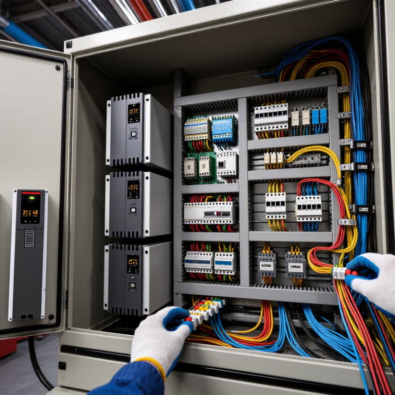
Learn MoreIndustrial equipment rarely operates alone. A variable-speed drive may switch rapidly beside a sensor cable, while a control cabinet shares space with relays, power supplies, and communication lines. These components can create electromagnetic interference or respond poorly to disturbances from nearby equipment. The result may be a false sensor reading, an unexpected reset, or unreliable data. Sometimes the cause is not obvious.
An Industrial EMC Solution addresses these risks through coordinated design, testing, and installation choices. It may include suitable cable routing, shielding, grounding, filtering, enclosure design, and component selection. The right combination depends on the equipment, its operating environment, and the paths through which interference can travel. Small details matter. A cable crossing a motor-power line, for example, can behave differently from one routed separately.
This article explains what an Industrial EMC Solution involves and how engineers assess its effectiveness. It also considers practical measures used in industrial control systems, from layout reviews to laboratory testing. Measurements and documented test conditions help support reliable decisions; assumptions alone do not. Still, no checklist can replace attention to a specific installation. A solution that works in a test setup may need adjustment on a noisy factory floor. That limitation is worth remembering.
An industrial EMC solution defines how equipment can operate without creating harmful electromagnetic interference or becoming unreliable when interference is present. Its scope may include a control cabinet, a production line, or connected machines across a wider facility. The boundary matters. A filter fitted to one drive cannot fix every problem elsewhere.
A practical assessment starts with the equipment, its cables, power supply, and operating environment. Engineers look for likely noise sources, such as variable-speed drives, switching power supplies, and long motor cables. They also consider sensitive circuits, including sensor inputs and communication links. Checks may include conducted and radiated emissions, immunity, bonding, shielding, cable separation, and grounding. The right measures depend on the installation; grounding methods that work in one cabinet may not suit another.
The work continues after design. Measurements during commissioning can reveal issues that a drawing missed, such as a shield connected at the wrong point or a cable routed beside a noisy conductor. Small details matter. Results should be recorded under realistic operating conditions, with clear limits and test setups. The scope is not always neat, though. A machine may pass a test alone and still behave differently once connected to a larger line. That gap deserves attention, not guesswork.
| Dimension | Operating Scope | Typical Measures | Relevant Evaluation |
|---|---|---|---|
| Conducted emissions | Unwanted electrical noise traveling through power or signal cables connected to industrial equipment. | Input filters, cable routing, common-mode chokes, shielding, and grounding improvements. | Emission limits and test methods depend on the product category and applicable standard. |
| Radiated emissions | Electromagnetic energy emitted through equipment enclosures, wiring, or connected assemblies. | Enclosure bonding, cable shielding, filtered interfaces, and reduction of high-frequency switching noise. | Measured in a suitable test environment using the limits specified for the equipment. |
| Electrostatic discharge (ESD) | Immunity to static discharges at accessible points and, where applicable, nearby surfaces. | Transient suppressors, controlled discharge paths, insulating barriers, and robust circuit layout. | IEC 61000-4-2 provides a commonly used ESD immunity test method. |
| Electrical fast transients and bursts | Immunity to repetitive fast transients associated with switching events and inductive loads. | Input filtering, cable separation, transient protection, and improved bonding. | IEC 61000-4-4 defines a commonly used test method. |
| Surge immunity | Protection against short-duration overvoltage events coupled onto power and signal connections. | Surge protective devices, coordinated insulation, protective earthing, and appropriate cable entry design. | IEC 61000-4-5 describes a surge immunity test method; required levels depend on the application. |
| Conducted RF immunity | Resistance to radio-frequency disturbances coupled onto cables and wiring. | Filtering, shielding, interface protection, and separation of sensitive circuits from noisy wiring. | IEC 61000-4-6 provides a commonly used conducted RF immunity test method. |
| Power-frequency magnetic fields | Immunity of equipment exposed to magnetic fields from power systems, transformers, or high-current conductors. | Equipment placement, loop-area reduction, magnetic shielding where appropriate, and robust sensor design. | IEC 61000-4-8 describes a power-frequency magnetic field immunity test method. |
| Voltage dips and interruptions | Equipment behavior during temporary reductions or interruptions in AC supply voltage. | Ride-through design, controlled shutdown, stored energy, and recovery logic. | IEC 61000-4-11 covers commonly used voltage dip and interruption test methods for applicable equipment. |
| Installation and system integration | The interaction of equipment, cabinets, cables, grounding, power distribution, and nearby sources of interference. | Cable segregation, equipotential bonding, shield termination, cabinet layout, and documented installation practices. | Assessment should reflect the intended installation and the equipment’s specified operating environment. |
| Standards and compliance planning | Selection of applicable EMC requirements based on equipment type, intended use, location, and market. | Requirements review, test planning, design verification, and records of results and configuration. | IEC 61000-6-2 and IEC 61000-6-4 are generic industrial immunity and emission standards where applicable; product-specific standards may take precedence. |

Note: Applicable limits, test levels, performance criteria, and required tests vary by product standard, intended environment, and regulatory market.
What Is an Industrial EMC Solution?
Which EMC Disturbances Threaten Industrial Equipment and Control Systems?
Industrial control systems face electromagnetic disturbances from both nearby equipment and the surrounding environment. A variable-frequency drive can send switching noise along power and signal cables. Long cable runs may then carry interference into sensors, PLC inputs, or communication links. Fast electrical switching can also create brief transients, while static discharge may reset a touchscreen or interrupt a control signal. Small events matter.
Surges from switching loads or lightning-related activity can stress power supplies and input circuits. Poor bonding or shared return paths may create ground-loop currents, causing unstable readings. Radio transmitters and wireless devices can introduce radiated interference, especially near unshielded cables or cabinet openings. The symptoms are not always obvious: a conveyor might stop only when a nearby motor starts, or a sensor may drift intermittently. These clues can be frustratingly inconsistent.
A useful investigation records when faults occur and what equipment is operating nearby. Check cable routing, enclosure bonding, grounding connections, and the separation between power and signal wiring. Measurements can help distinguish conducted noise from radiated interference, but one test rarely explains every symptom. A clean-looking cabinet can still have a poor cable termination. That diagnosis is not always neat. Practical EMC work often means testing one change at a time and documenting what actually improves system behavior.
What Is an Industrial EMC Solution?
IEC 61000-4-2 defines a repeatable method for evaluating electrostatic discharge immunity. Its Level 4 test specifies 8 kV contact discharge and 15 kV air discharge. These figures come from the standard’s test-level table, not from a prediction of every factory event. At 8 kV, the specified first current peak is 30 A, with a rise time of 0.8 nanoseconds (IEC 61000-4-2:2008, Table 1). Fast, intense pulses can upset control electronics.
Contact discharge places the electrode directly against a conductive test point. Air discharge approaches an insulating surface until a spark jumps. The standard calls for repeated applications at selected points and both polarities. Test locations might include a metal enclosure seam, a keypad edge, or a sensor connector. Small details matter.
For an industrial EMC solution, the goal is not merely to pass a voltage check. Engineers should monitor resets, false sensor readings, and communication loss during testing. A unit that survives one location may still fail near a different seam. That deserves attention. The IEC procedure provides a consistent benchmark, but it cannot reproduce every cable layout, humidity level, or operator action. Treating a passing result as a guarantee would be a mistake.
At Level 4, IEC 61000-4-2 specifies a test level of 8 kV for contact discharge and 15 kV for air discharge. These are voltage magnitudes; testing typically applies both positive and negative polarities.
An industrial EMC solution helps equipment operate reliably amid electrical noise while limiting disturbances it creates. IEC 61000-6-2:2016 sets generic immunity requirements for industrial environments. It points to tests for electrostatic discharge, radiated radio-frequency fields, electrical fast transients, surges, and voltage dips. These tests use defined methods from the IEC 61000-4 series. Test levels depend on the applicable port and installation conditions; passing one test does not prove immunity to every site disturbance. Field conditions vary. A motor cable running beside a sensor lead can create a practical problem that a tidy laboratory setup may not reveal.
IEC 61000-6-4:2018 sets generic emission requirements for industrial environments, including limits for conducted and radiated disturbances. Measurements follow specified methods, so results can be compared with the relevant limits. Together, the standards define two sides of the same engineering task: withstand interference and avoid adding excessive noise to nearby equipment. The International Energy Agency’s Electricity 2024 report says global electricity demand grew 2.2% in 2023 and forecasts average annual growth of 3.4% through 2026. More electrified systems make careful EMC design increasingly important, though demand growth alone cannot predict interference at a particular plant. That matters. Engineers should check the equipment’s intended environment, cable routes, grounding, and operating modes, then verify performance through applicable tests. A compliant result is useful evidence, not a substitute for reviewing real installation details.
An industrial EMC solution is not just a metal enclosure. It is a controlled path for unwanted energy. Shielding works only when seams, doors, cable entries, and conductive finishes maintain continuity. A narrow gap around a panel can become a leakage point. Filtering must sit at the enclosure boundary; otherwise, an unfiltered cable can carry noise past the shield. Grounding also needs a short, low-impedance bond. A long wire may look solid but behave poorly at high frequencies. Small details matter.
Testing checks whether these measures hold under defined conditions. IEC 61000-4-3:2020 specifies radiated RF immunity testing from 80 MHz to 6 GHz. IEC 61000-4-4:2012 defines fast-transient testing using a 5/50 ns waveform, with repetition rates that include 5 kHz and 100 kHz. These are test conditions, not automatic proof of fitness for every factory. Test the assembled equipment, with representative cables and operating loads. Then inspect the setup. A quiet laboratory result can miss a poorly bonded field installation. That is an uncomfortable limitation, but a useful one: EMC performance depends on installation as much as component choice. Retest after meaningful changes to wiring, enclosure panels, or grounding. Do not assume a filter fixes every problem.