2026 Best Optical Attenuator Types for Global Buyers
The 2026 optical network will demand tighter power control, not simply higher bandwidth. AI clusters, coherent pluggables, and dense data-center links are increasing the need for predictable optical budgets. LightCounting’s recent data-center optics analyses show strong growth in high-speed optical interconnect demand. Dell’Oro Group also reports sustained investment in optical transport and data-center connectivity. These trends indirectly strengthen the market for precision Optical Attenuator solutions.
The choice is practical. Fixed attenuators suit stable links. Variable optical attenuators support commissioning, testing, and changing signal levels. Inline, bulkhead, connectorized, MEMS, and electronically controlled designs each serve different installation conditions. Wavelength range matters. So do return loss, insertion loss, power handling, and calibration stability. IEC 60869-1 and ITU-T G.671 provide useful technical references for evaluating attenuation performance.
Dr. Govind P. Agrawal, a leading fiber-optics researcher, states, “The received power must remain within the dynamic range of the receiver.” This principle remains central when selecting an Optical Attenuator. A low-cost device may appear adequate on a laboratory bench. It may drift inside a warm rack. It may also create unexpected reflections in a dense patching environment.
Still, market reports rarely separate attenuator revenue from broader passive optical components. That limitation deserves attention. Global buyers should compare measured data, not attractive catalog claims. The best 2026 solution will balance attenuation accuracy, connector compatibility, environmental endurance, and long-term serviceability. Small details matter here. One incorrect dB value can distort an entire link budget.
Optical Attenuator Fundamentals and Operating Principles
Optical attenuators reduce optical power without changing the signal path. Their basic equation is simple: attenuation equals 10 log10(Pin/Pout), measured in decibels. A 10 dB attenuator passes about 10% of the input power. This control prevents receiver overload and stabilizes optical links during testing.
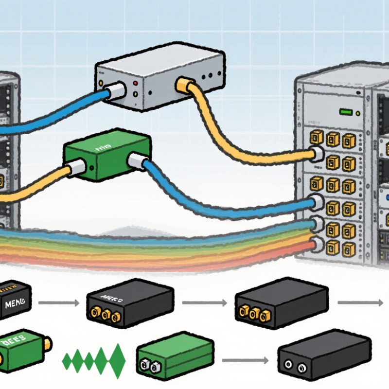
Common types include fixed, variable, inline, plug-style, and connector-mounted attenuators. Fixed devices use absorbing films or controlled air gaps. Variable optical attenuators adjust power through mechanical movement, micro-electromechanical structures, or liquid-crystal control. In field testing, wavelength matters. A device rated at 1310 nm may not deliver the same loss at 1550 nm. Small errors matter. Always check insertion loss, return loss, power handling, and wavelength range against IEC and ITU-T specifications.
Demand for predictable attenuation follows fiber expansion. The ITU Facts and Figures 2024 report estimates that 5.5 billion people were online, increasing pressure on network capacity and optical testing. OECD broadband statistics also show fiber represented roughly 42% of fixed broadband subscriptions across member economies in late 2023. These figures do not determine attenuator demand directly, but they explain the need for repeatable power control across dense networks. A practical buyer should request measured tolerance, not only a nominal “10 dB” label. Measure twice. A connector can add unexpected loss, and real installations rarely behave like laboratory diagrams.
Main Optical Attenuator Types for Different Applications
2026 Best Optical Attenuator Types for Global Buyers
Main Optical Attenuator Types for Different Applications
Fixed optical attenuators suit stable fiber links with predictable power levels. They reduce optical strength by a set value, such as 3 dB, 5 dB, or 10 dB. Field technicians often use them during network commissioning. Their simple structure supports consistent performance and easy installation. Connector-style attenuators work well inside patch panels and compact distribution boxes. Check connector compatibility, operating wavelength, return loss, and power limits before ordering.
Variable optical attenuators provide adjustable control for laboratory testing, receiver calibration, and changing network conditions. Manual models are practical for occasional adjustments. Electrically controlled versions support automated test systems and remote monitoring. For dense data links, programmable attenuation can help balance channels during commissioning. However, adjustment accuracy may decline at extreme settings. This detail is easy to overlook.
Inline attenuators are useful when equipment must remain connected without changing the entire cable route. They fit between fiber assemblies and help correct excessive input power. Polarization-dependent loss and insertion loss should be measured, not assumed. High-power systems may require attenuators with stronger thermal handling and wider wavelength coverage. In my experience, buyers sometimes select the lowest price first, then discover poor stability during temperature changes. A better approach compares application needs, safety margins, connector polish, and verified test data. The ideal type may change after real network measurements.
2026 Best Optical Attenuator Types for Global Buyers
Main optical attenuator types for different applications. The chart compares representative attenuation ranges commonly used in fiber-optic testing, telecom networks, receiver protection, and automatic power control.
Fixed attenuators are selected for stable link balancing and receiver overload protection. Mechanical variable attenuators suit laboratory testing, while MEMS and electronic VOAs are preferred for dynamic power equalization, monitoring, and closed-loop optical control. Actual limits depend on wavelength, connector type, polarization, optical return loss, and product specification.
Key Specifications Global Buyers Should Compare
Global buyers should compare optical attenuators by measured performance, not only by price or connector type. Cisco’s Annual Internet Report projected global IP traffic to reach 396 exabytes monthly by 2022, compared with 122 exabytes in 2017. That growth increases pressure on stable optical power control. Check the attenuation range, wavelength window, insertion loss, return loss, and power rating. A 0–30 dB range may suit laboratory testing, while fixed 3 dB or 10 dB units often fit predictable links. Small differences matter.
Test conditions matter too. IEC 61300-3-4 defines methods for measuring insertion loss, so suppliers should provide test wavelengths and uncertainty values. ITU-T G.671 also offers a useful reference for optical component performance. Compare accuracy across temperature, polarization-dependent loss, and repeatability after connector cleaning. A strong specification sheet includes these details. Missing data is a warning.
I have seen buyers select a variable attenuator because it offers flexibility, then discover its higher insertion loss reduces their power budget. That mistake is easy to make. For dense fiber panels, compare connector polish, housing size, operating temperature, and maximum optical power. For automated networks, check control resolution, switching time, and calibration records. Cisco’s traffic forecast is old, but the lesson remains relevant: networks keep expanding. A neat datasheet is not proof. Independent test evidence is better.
How to Select the Right Attenuator for Each Fiber Network
Selecting the right optical attenuator starts with the network, not the product label. A fixed attenuator suits stable links with predictable power levels. A variable attenuator works better during commissioning, testing, or fault isolation. For patch-panel integration, choose a connectorized or plug-in model that matches the existing interface.
Wavelength matters. A device rated for 1310 nm may not perform equally at 1550 nm. Check attenuation accuracy, return loss, and maximum optical power before installation. Dense fiber links may need low-reflection components, especially near sensitive receivers. Outdoor cabinets also require protection against moisture, temperature changes, and repeated handling. Small details matter.
Field experience shows that excessive attenuation can hide a weak transmitter or create an unstable margin. Measure the transmitter output and receiver range with a calibrated optical power meter. Then calculate the required loss, including connectors and splices. Do not rely on nominal values alone. A practical admission: network records are sometimes incomplete. Inspect the connector type and polish physically when documentation conflicts. For high-density systems, space and bend-radius limits can influence the final choice more than price. In temporary test setups, a variable model saves time, but it may introduce adjustment errors. Mark the tested setting clearly. Recheck it after maintenance.
International Purchasing, Compatibility, and Quality Considerations
2026 Best Optical Attenuator Types for Global Buyers
International buyers should match the attenuator type to the measurement task. Fixed attenuators offer stable loss for testing and network balancing. Variable attenuators support repeated adjustment during commissioning. Step attenuators provide defined settings, which help laboratories compare results. Inline fiber attenuators suit compact links and field installations.
Compatibility requires more than connector shape. Confirm the operating wavelength, attenuation range, maximum optical power, and fiber mode. Check connector polish, return loss, insertion loss, and polarization sensitivity. A connector may fit physically but still create excessive reflection. Regional suppliers may use different test conditions, so request the calibration method and measurement uncertainty. That detail is often missing.
Tips: Order samples before volume purchasing. Test them with your actual wavelength and transceivers. Ask for serial-level test reports, traceable calibration, and environmental ratings. Inspect protective caps and packaging after long-distance shipping. Small scratches can affect performance.
From practical procurement work, I have found that a low purchase price can hide higher integration costs. A specification sheet can still mislead when tolerances are unclear. Buyers should compare measured values, not only nominal attenuation. Consider spare units for projects with difficult replacement schedules. I would also review temperature performance, because indoor testing may not represent a hot cabinet or cold warehouse. My earlier assumption that all variable attenuators behave similarly was wrong; adjustment repeatability can differ noticeably. Quality control must be verified, not simply promised.